Weld Symbols In Drawings
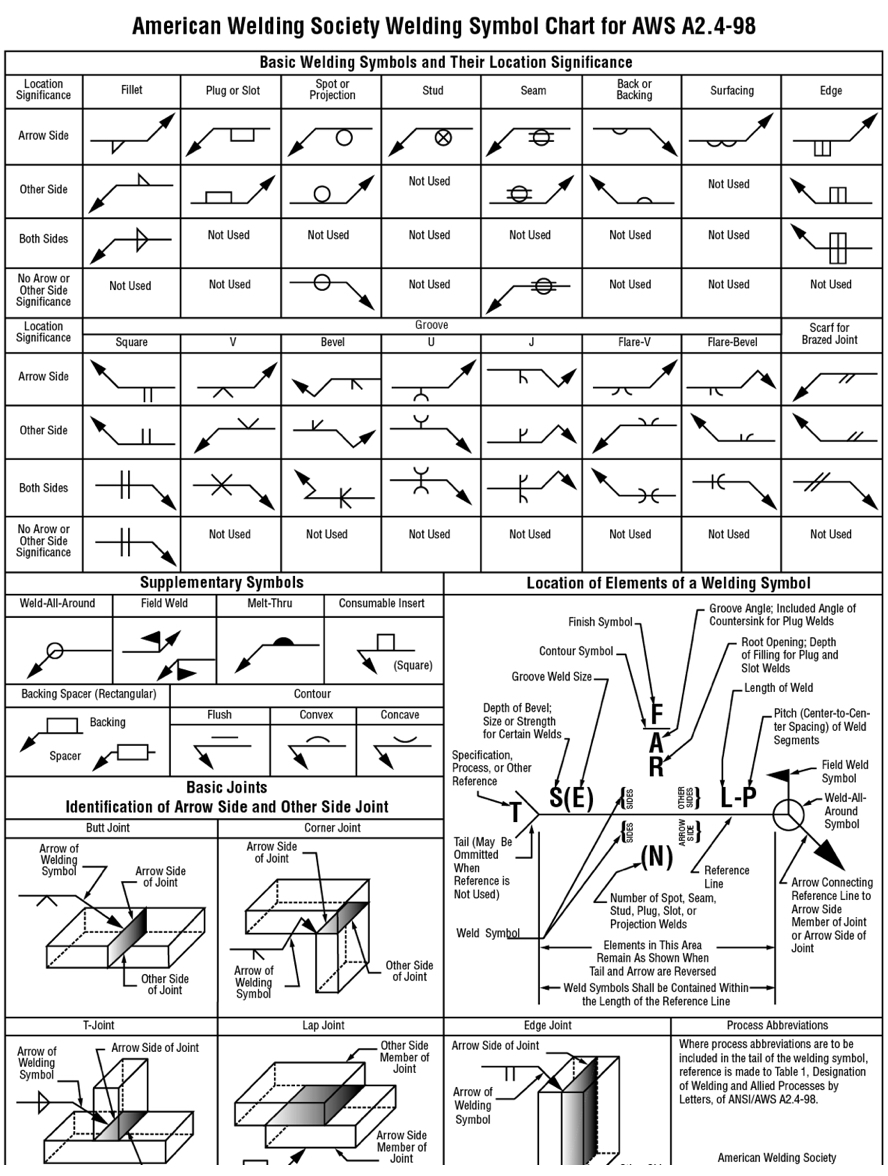
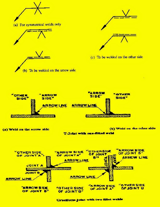
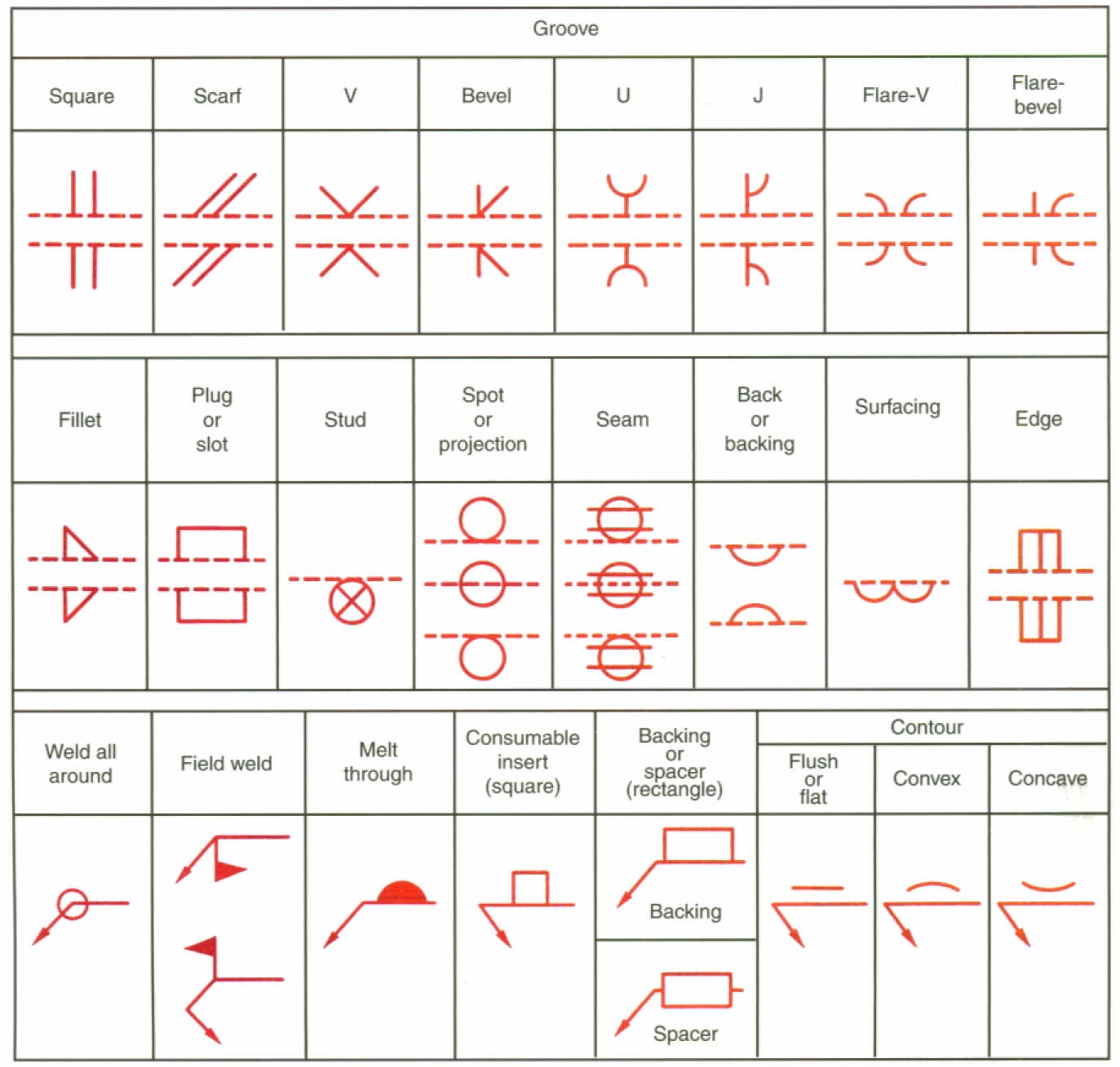
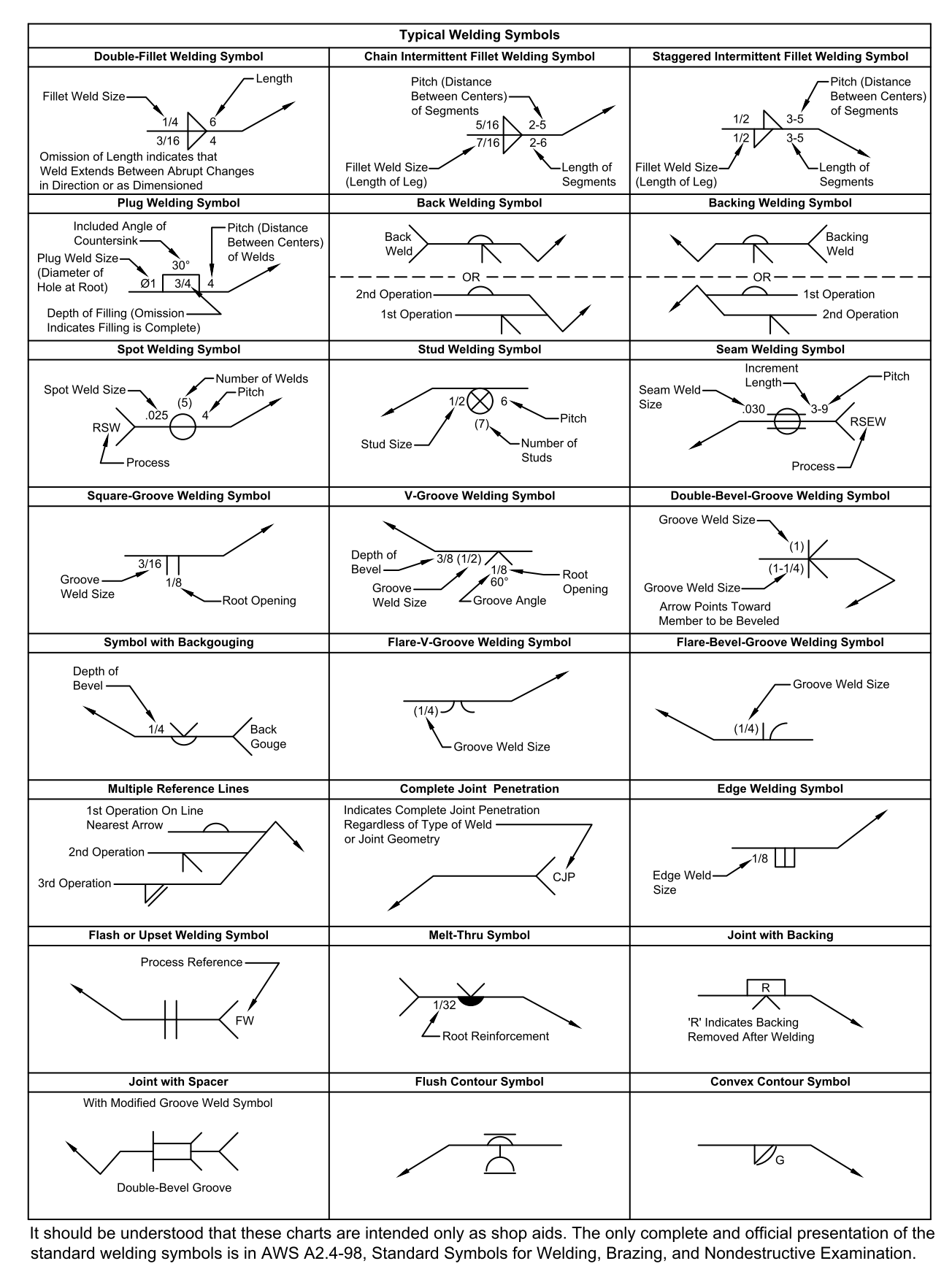
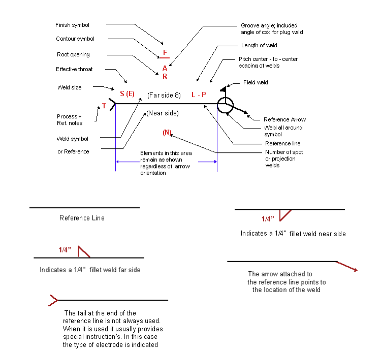
Weld Symbols In Drawings - Web welding symbols include an arrow, reference line, and optional tail to denote specifics of the welding technique or filler material. Web a welding symbol is what you see on the fabrication drawing. These symbols are usually found in fabrication and engineering drawings. Web weld symbols come with an arrow that points to the direction of the drawing where a weld needs to be made. Web what is a welding symbol & its meaning? The arrow line is connected to a leader line which is intersected with a horizontal reference line. The base platform, base butt weld symbols, other base symbols, and supplementary symbols. A download comparing iso and america weld symbols. Welding symbols ensure the welder knows what the engineers and. It communicates the location of welding, the type of welding, and all the other details required by the fabricator to execute the fabrication. Web weld symbols can be confusing if you don't know what you're looking at. This was a very basic introduction to weld symbols. These symbols indicate the welding methods, weld form, weld size, and other technical details necessary for the fabrication process. The sketch of welding symbols becomes a headache if you are not familiar with the basics of these symbols. Web each weld symbol is explained individually, with its weld profile alongside it. Web detailed part drawings may contain many welding symbols. Web weld symbols are a very useful way of communicating welding requirements from the design office to the shop floor. Web during metal joining processes, weld symbols are meant to indicate different parts of the process. Web welding symbols are the integral part and the basic requirements for fabrication as they provide vital information for the welding joint location, weld size (throat or leg length, depth of penetration) & length, weld type & quality requirements for the fabrication or construction drawing. A download comparing iso and america weld symbols. Web using welding symbols to indicate necessary welding information on engineering drawings offers several advantages: Web the welding symbol is made of several parts including the reference line, arrow, and weld symbol when required. The arrow line is connected to a leader line which is intersected with a horizontal reference line. Therefore, you can get a weld symbol that. Web. Web welding symbols furnish with a procedure to place every information on the drawings. Therefore, you can get a weld symbol that. Web welding symbols are the integral part and the basic requirements for fabrication as they provide vital information for the welding joint location, weld size (throat or leg length, depth of penetration) & length, weld type & quality. It communicates the location of welding, the type of welding, and all the other details required by the fabricator to execute the fabrication. The arrow line is connected to a leader line which is intersected with a horizontal reference line. Web weld symbols are a very useful way of communicating welding requirements from the design office to the shop floor.. This was a very basic introduction to weld symbols. How many welding symbols are there? Web 9 spot, seam, stud welding symbols. Welding symbols are used to indicate desired welding & brazing details on the fabrication drawings. Web a welding symbol is what you see on the fabrication drawing. The base platform, base butt weld symbols, other base symbols, and supplementary symbols. By understanding the types of welds and their corresponding symbols, as well as the structure of a welding symbol, you'll be able to decipher even the most complex welding diagrams. Web what is a welding symbol & its meaning? The symbols in this book are a representation. Web hence, welding symbols are widely used in engineering drawings by welders and engineers to convey essential information like type of the weld, size of the weld, location of the weld and other supplementary information as well. Elements of a welding symbol. Welding symbols ensure the welder knows what the engineers and. The use of symbols can significantly reduce the. Achieving a training certificate of a professional welder is insufficient until you know how to read the draftsman’s drawing prior to welding. The sketch of welding symbols becomes a headache if you are not familiar with the basics of these symbols. Web weld symbols come with an arrow that points to the direction of the drawing where a weld needs. Why do we need to specify welds? A welding symbol may appear in any view on the drawing. These symbols indicate the welding methods, weld form, weld size, and other technical details necessary for the fabrication process. There are two systems that are used for interpretation, and four sections of different symbols explained in this article: Web 9 spot, seam,. The use of symbols can significantly reduce the time needed to complete a drawing compared to drawing the weld as it will appear. Web weld symbols come with an arrow that points to the direction of the drawing where a weld needs to be made. Web during metal joining processes, weld symbols are meant to indicate different parts of the. Web welding symbols furnish with a procedure to place every information on the drawings. A welding symbol may appear in any view on the drawing. There are two systems that are used for interpretation, and four sections of different symbols explained in this article: All the information you need as a welder is in the welding symbol. A weld symbol. Welding symbols ensure the welder knows what the engineers and. This was a very basic introduction to weld symbols. Web a welding symbol is what you see on the fabrication drawing. A download comparing iso and america weld symbols. The spot weld symbol is simply a circle that may be placed above, below, or centered on the reference line. The symbols in this book are a representation of what weld and welding symbols look like. Web during metal joining processes, weld symbols are meant to indicate different parts of the process. A weld symbol would differentiate between two sides of a joint using arrows and the spaces on top and under the reference line. When the symbol is centered on the reference line this indicates that there is no side significance. How many welding symbols are there? The use of symbols can significantly reduce the time needed to complete a drawing compared to drawing the weld as it will appear. Web hence, welding symbols are widely used in engineering drawings by welders and engineers to convey essential information like type of the weld, size of the weld, location of the weld and other supplementary information as well. Training programs that we have gone thru or put on for customers range between 4 and 16 hours. Web detailed part drawings may contain many welding symbols. Whenever two or more pieces are joined by welding, the assembled item is called a weldment. Web welding symbols are the integral part and the basic requirements for fabrication as they provide vital information for the welding joint location, weld size (throat or leg length, depth of penetration) & length, weld type & quality requirements for the fabrication or construction drawing.
Welding Symbols with Figures PAKTECHPOINT

Understanding the Basic Welding Symbols
Drawing and Welding Symbol Interpretation Welding Class
Weld Symbols Chart American Welding Society DWG file Autodesk_AutoCAD
TIMES OF MECHANICAL DESIGN WELD SYMBOLS USED IN DESIGN
Welding Inspection Weld Symbol

Weld Symbols
Welding Symbols Chart Printable Customize and Print
Understanding the Welding Symbols in Engineering Drawings Safe Work

Understanding the Basic Welding Symbols
Why Do We Need To Specify Welds?
Elements Of A Welding Symbol.
A Welding Symbol May Appear In Any View On The Drawing.
Consider The Following Image Is Given To A Welder.
Related Post: